Blinking a LED is the “Hello, world” of embedded programming and most development board have an integrated LED. This makes it easier to run a basic piece of code, without having to hookup any external components.
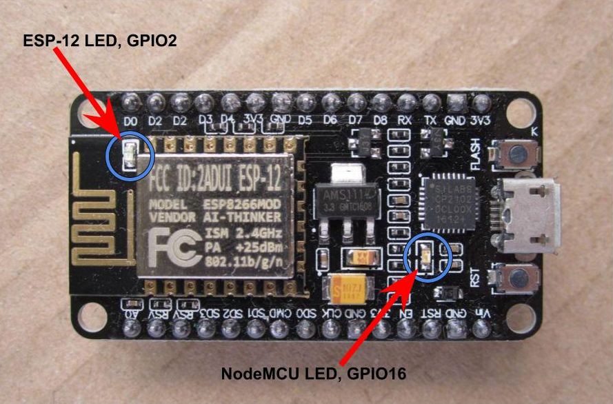
The NodeMCU ESP8266 board has two of those LEDs! One on the NodeMCU PCB and another on the ESP-12 module’s PCB:
Comparison Table
| NodeMCU LED | ESP-12 LED | |
|---|---|---|
| Color | Blue | Blue |
| SMD Footprint | 0603 | 0603 |
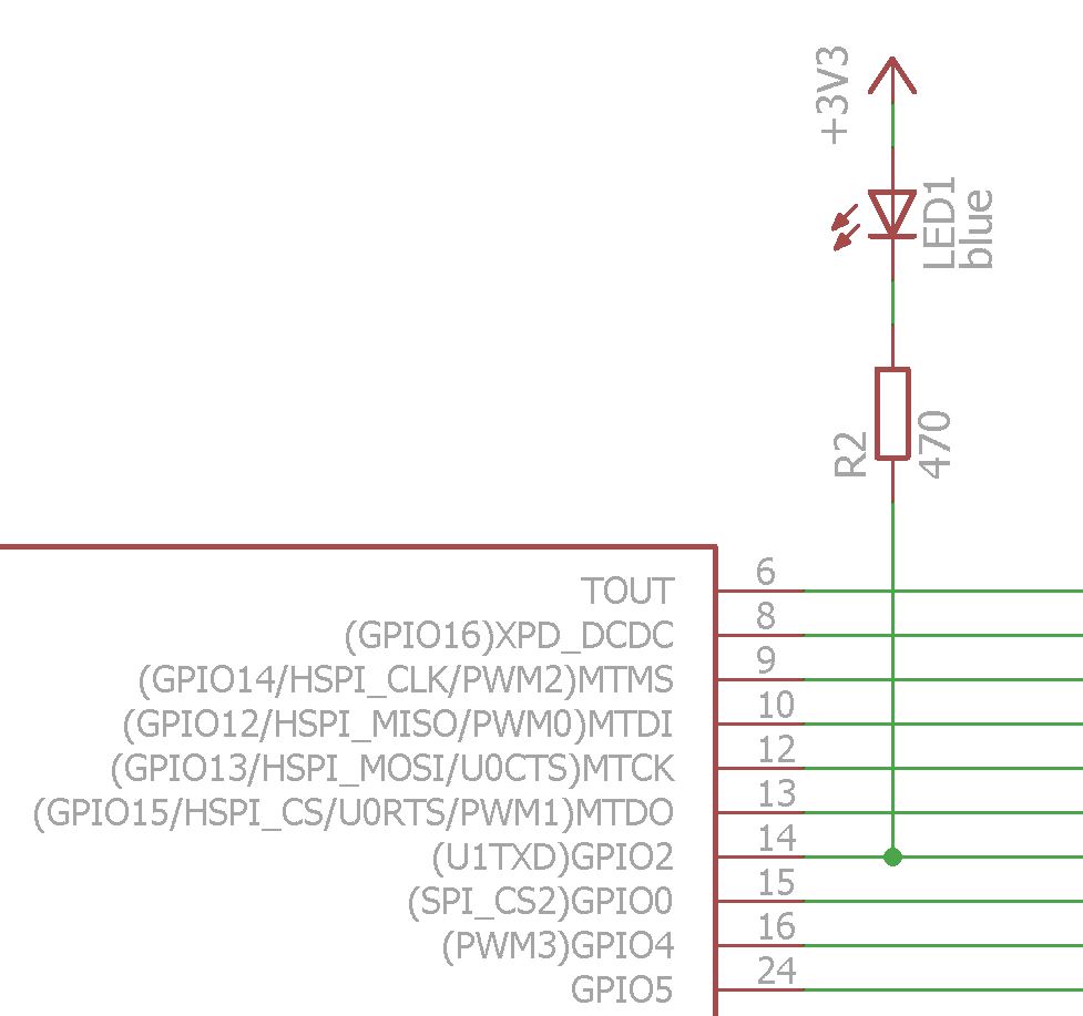
| Pin | GPIO16 | GPIO2 |
| Pin Functions | USER, WAKE | U1TXD |
| Pin Silkscreen | “D0” | “D4” |
| Current-limiting Resistor | 470 ohm | 470 ohm |
| Sketch Pin Numbers | 16, D0, LED_BUILTIN, BUILTIN_LED | 2, D4 |
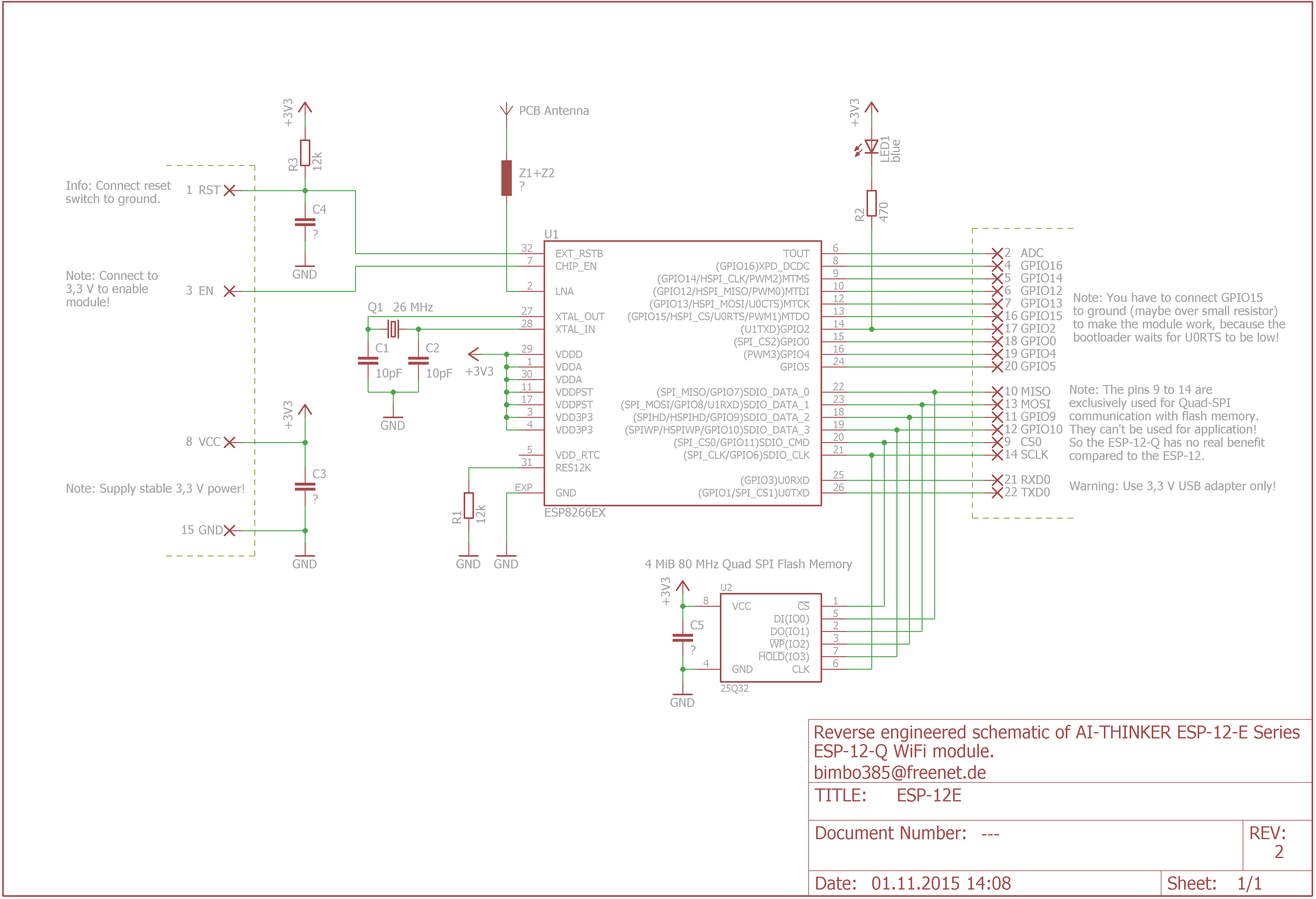
| Schematic | 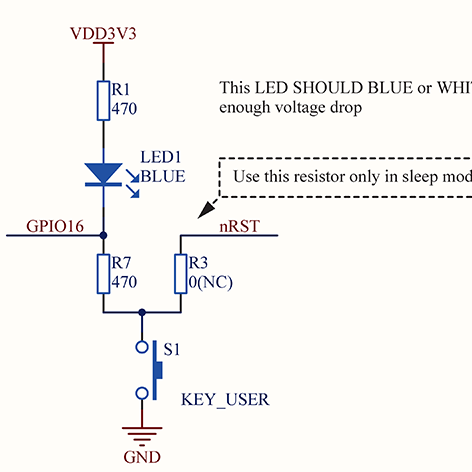 |
 |
Notes
Both LEDs operate in “inverted” mode, with regard to the pin levels - when the pin is HIGH, the LED is off; when the pin is LOW, the LED is on.
The LED on GPIO2 flashes during ESP programming, as it is connected to the U1TXD pin.
NodeMCU LED Blink
void setup() {
  pinMode(LED_BUILTIN, OUTPUT);     // Initialize the LED_BUILTIN pin as an output
}

void loop() {
  digitalWrite(LED_BUILTIN, LOW);   // Turn the LED on by making the voltage LOW
  delay(1000);                      // Wait for a second
  digitalWrite(LED_BUILTIN, HIGH);  // Turn the LED off by making the voltage HIGH
  delay(2000);                      // Wait for two seconds
}
ESP-12 LED Blink
void setup() {
  pinMode(2, OUTPUT);     // Initialize GPIO2 pin as an output
}

void loop() {
  digitalWrite(2, LOW);   // Turn the LED on by making the voltage LOW
  delay(1000);            // Wait for a second
  digitalWrite(2, HIGH);  // Turn the LED off by making the voltage HIGH
  delay(2000);            // Wait for two seconds
}